
Occupancy and Vacancy Sensors
Reprinted with permission of the Lighting Controls Association, 2017. All rights reserved. To learn more about controls, visit their website.
Occupancy and vacancy sensors are devices that detect when a space is unoccupied and accordingly automatically turn OFF (or dim) the lights, thereby saving energy. The device may also turn the lights ON automatically upon detecting the presence of people, providing convenience and a potential security aid. According to the Lawrence Berkeley National Laboratory, occupancy-based strategies can produce average lighting energy savings of 24%.
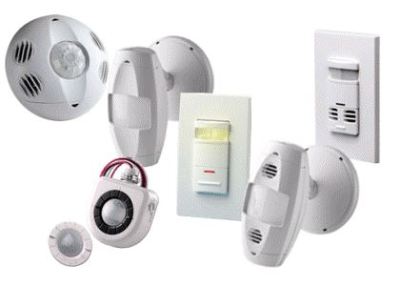
Due to their relative simplicity and high energy-savings potential, coupled with energy code mandates, these sensors are a staple in new construction. They are also a common control feature in retrofit projects.
This article provides information that can be used to select an appropriate sensor technology and product features based on a given application’s characteristics. It is based on an updated Education Express course that will be posted shortly
TECHNOLGY
Inputs
Occupancy sensors may be specified as manual-, partial- or full-ON devices.
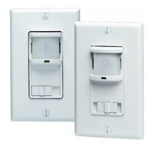
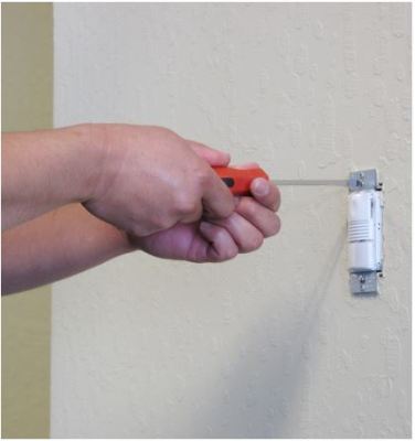
The majority of commercial building energy codes require manual- or partial-ON operation. Manual-ON sensors (also called vacancy sensors) require the occupant to turn the lights ON using a manual switch, which may be integral to the sensor (shown here is an example). Partial-ON sensors activate the lights to a designated level such as 50%, and the occupant then uses a switch to bring the lights to full output. Full-ON sensors activate the lights at full output.
Manual- and partial-ON sensors tend to save more energy because the occupant may want to leave the lights OFF or at a lower level. Full-ON sensors provide convenience, which may be regarded as an amenity.
Outputs
Occupancy and vacancy sensors may turn the lights OFF or reduce the lighting via stepped switching or dimming. While ON/OFF is more common, light reduction is well suited to applications where the lights must stay ON but are frequently unoccupied, such as this stairwell, or where the lamp does not start quickly, as in the case of HID lamps.

Coverage Area and Pattern
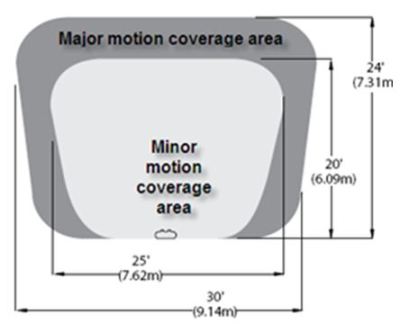
The sensor’s sensitivity defines at what distance it can detect major (i.e., body) and minor (i.e., hand) motion. The resulting coverage is expressed as coverage area and pattern. Coverage area defines the boundaries within which the sensor can detect motion. Coverage shape is the resulting shape of these boundaries, which may be a circle, rectangle, ellipse, tear drop, etc.
NEMA WD-7 offers testing and reporting methods for coverage areas and patterns, which compliant manufacturers report in their literature. This allows meaningful product comparison. The value is typically a maximum, which may be adjusted based on sensitivity setting, room dimensions, mounting height, presence of obstacles and other factors.
Shown here is a coverage pattern for a wall switch ultrasonic sensor.
Sensing Technology
The most common single-technology methods are passive infrared (PIR) and ultrasonic (US). Dual-technology (DT) sensors combine PIR with ultrasonic or acoustic sensing. Other methods include microwave sensors, which emit low-power microwaves and detect changes in occupancy, and camera-based sensors, which take multiple images of the coverage area per second. Researchers are now exploring even more ways to detect occupants, such as light-differential sensing.
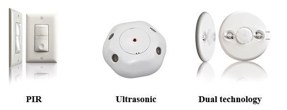
Passive infrared
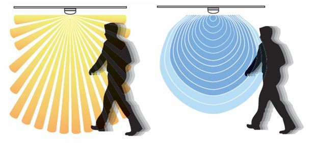
PIR sensors react to the movement of heat emitted by people in motion. They detect motion within a coverage area that requires a line of sight; they cannot “see” occupants behind obstacles or glass.
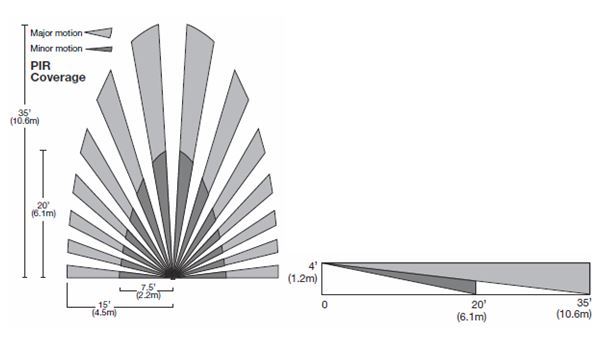
The detection mechanism is a multi-faceted lens that defines its coverage area as a series of discrete fan-shaped zones (see below example for a wall switch-mounted sensor, recommended for a maximum 15-ft. x 12-ft. area). The lens also determines the size of motion it is best suited to detect.
The sensor detects motion when an occupant crosses these zones, making it more sensitive to motion occurring lateral to the sensor. The gaps between the zones widen with distance, which results in sensitivity decreasing the farther the occupant is from the sensor. Most PIR sensors are sensitive to full body movement up to about 40 ft. but are sensitive to hand movement, which is more discrete, up to about 15 ft.
Ultrasonic
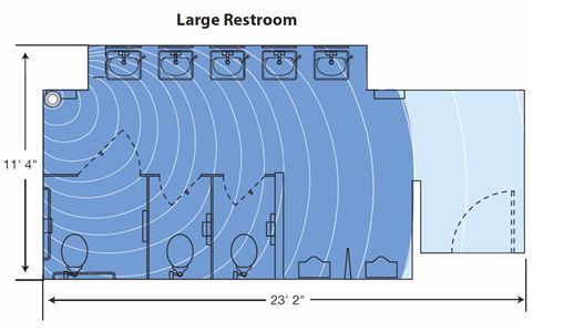
US sensors emit an ultrasonic high-frequency signal throughout a space, monitor the frequency of the reflected signal, and interpret change in frequency as motion. Alternately, they can set up a standing wave and look for changes in both amplitude and frequency due to motion. The frequency of the waves typically is well above (32-40 kHz) what the normal ear can detect (20 kHz) to avoid incompatibilities with devices such as hearing aids. These sensors do not require a direct line of sight (coverage is volumetric), making them ideal for applications such as public restrooms with multiple stalls.
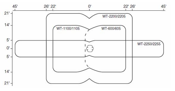
Able to detect minor motion at a distance up to 25 ft., these sensors are highly sensitive. Shown here are coverage patterns for four US sensors suitable for different applications, including 180- to 360-degree coverage, and including different-sized rooms and a hallway.
Dual Technology
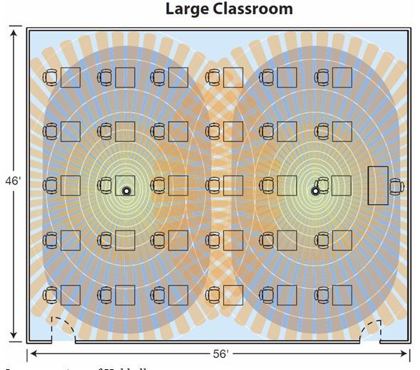
DT sensors utilize two detection methods to increase reliability in applications where a higher degree of detection is desirable (e.g., occupants are not moving for long periods of time), such as classrooms.
Most manufacturers offer sensors that combine ultrasonic and PIR technologies. The lights activate only when both technologies detect the presence of people. Only one technology is needed to hold the lights ON.
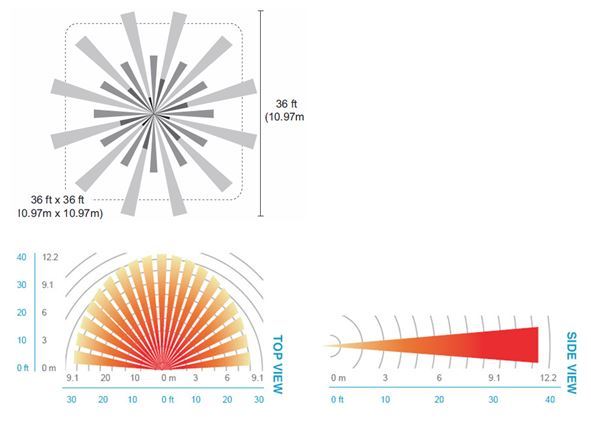
Another DT sensor combines PIR with acoustic detection, called passive DT because no waves emit into the space. The sensor’s microphone filters out white noise to focus on sharp variations characteristic of local occupant activity. Shown here are coverage patterns for a ceiling-mounted DT sensor (top) and a wall switch-mounted passive DT sensor (bottom).
Mounting Packages
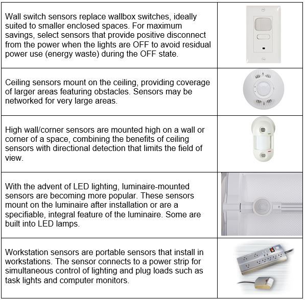
Sensors may be configured for ceiling, high wall/corner, wall switch (wallbox), workstation and luminaire mounting.
Power and Communication
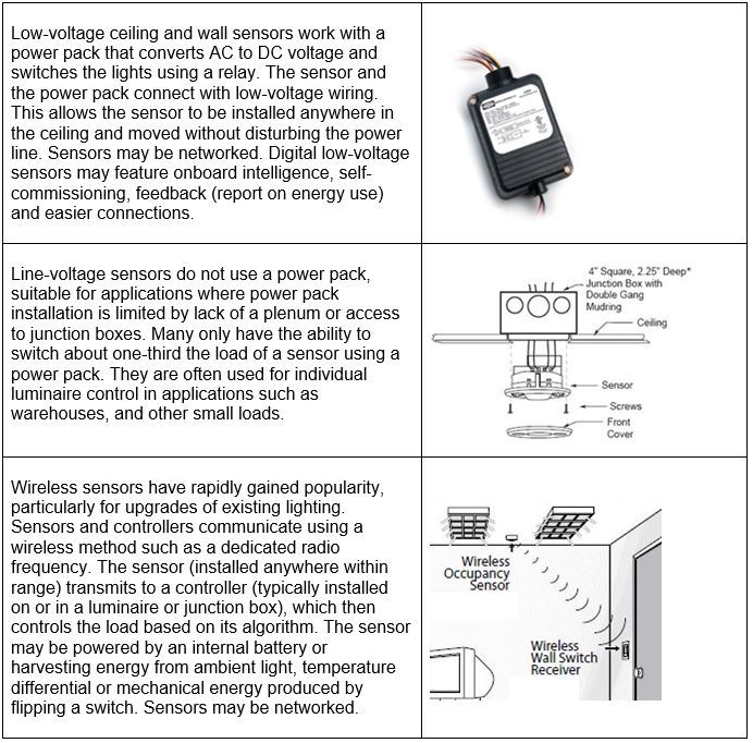
Sensors may be low- or line-voltage or wireless.
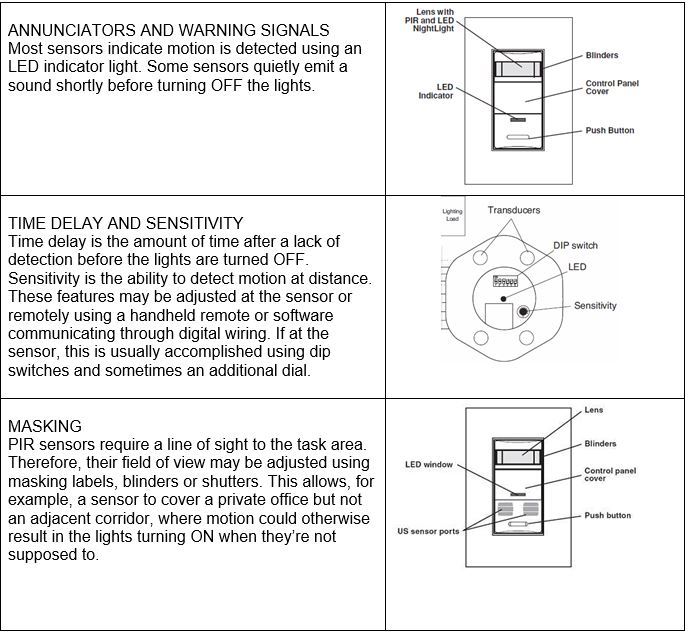
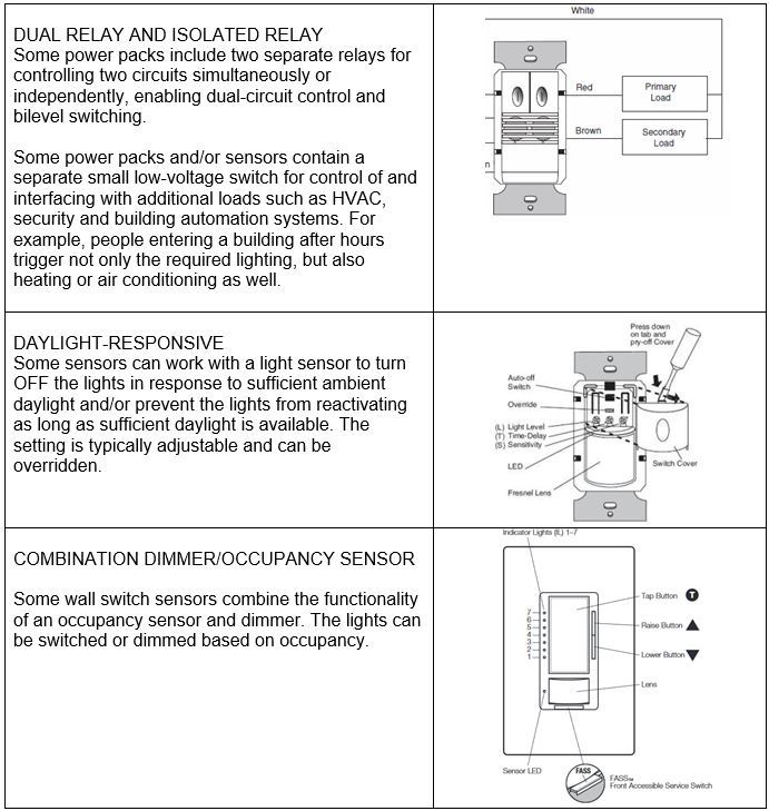
Special Features
Accessories
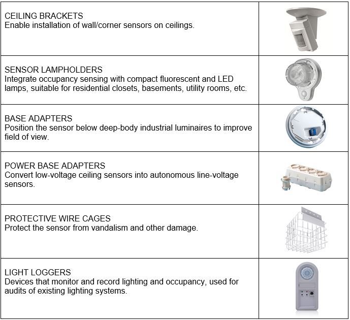
APPLICATION
Occupancy and vacancy sensors are ideally suited to installation in smaller, enclosed spaces:
- larger spaces using zoned/networked or individual luminaire control
- spaces that operate on an unpredictable schedule
- spaces that are intermittently occupied—that is, left unoccupied for two or more hours per day
- stairwells, corridors and similar spaces where the lighting must remain ON all day but are frequently unoccupied (light reduction)
Ideal applications include offices, classrooms, copy rooms, restrooms, storage areas, conference rooms, warehouse aisles, break rooms, corridors, filing areas and other spaces.
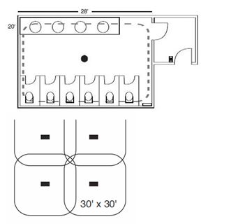
Two examples are shown here, a public restroom (top) with a single sensor and an open office (bottom) with multiple networked sensors. In the restroom, a ceiling DT sensor is placed about 2 ft. out from the stall door to cover the space. In the open office, multiple ceiling US sensors are wired in parallel and networked to cover the entire space as a single load. Only one sensor is required to turn the lights ON and keep them ON. Note a minimum 20% overlap in coverage area is recommended to ensure reliability of detection.
Energy Codes

Most commercial building energy codes require lighting be turned OFF or reduced when it is not being used. These codes apply to new construction and renovation projects and, in some states, lamp-plus-ballast retrofits as well. The majority of codes now specifically require sensors in a wide range of spaces. Increasingly, codes mandate use of manual- or partial-ON sensors. The maximum time delay is trending from 30 to 20 minutes. See our Energy Codes course for information that may be applicable to your project.
PIR Sensors
PIR occupancy sensors sense the difference in heat between moving people and their background. They can be installed on ceilings or walls, including as a wall switch replacement, and used in both indoor and outdoor applications. They are well suited to:
- smaller, enclosed spaces such as private offices, utility closets and storage rooms
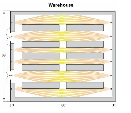
- spaces requiring limited coverage such as warehouse aisles and corridors
- relatively confined outdoor spaces such as building perimeter lighting.
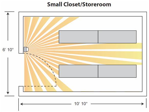
PIR sensors should be located so that they have an unobstructed view of the primary task area. (While line-of-sight sensing can be limiting, it also enables the field of view to be limited at the factory by design or in the field through adjustment.) If full- or partial-ON, they should turn the lights ON immediately when an occupant enters the room.
These sensors are less sensitive than ultrasonic sensors; sensitivity decreases the farther away the occupant is from the sensor. They are most sensitive to motion lateral to the sensor. The coverage area should be limited so that only the lighting in the designated space is controlled.
Because PIR sensors respond to heat differential, such differential must exist. Additionally, to prevent false-ON switching (although the condition is rare in this case), they should not be mounted within 6-8 ft. of HVAC air diffusers and other heat sources.
US Sensors
US sensors emit high-frequency sound waves into the space and detect occupancy from changes in the frequency of returning reflections, or they may set up a standing wave and measure both frequency shift and amplitude. They can be installed on ceilings or walls, including as a wall switch replacement, typically in indoor applications. Although they are an active technology (emit energy into the space), properly designed devices will not interfere with local devices such as hearing aids. They are well suited to applications requiring greater sensitivity and reliability, open indoor spaces, and spaces with obstacles. Suitable applications include open offices, private offices, bathrooms, classrooms and conference rooms.
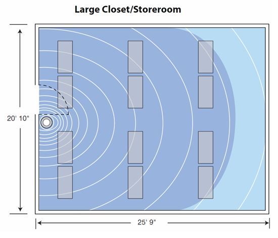
US sensors do not require a line of sight to the primary task area. They can “see” around corners and obstacles, and have volumetric coverage—that is, they monitor the entire space, not just what is within the field of view. However, the sensor’s field of view cannot be limited after installation.
Ultrasonic sensors should be located so that they lights turn ON as soon as a person enters the space. They are more sensitive than PIR sensors, ideal for applications with minor body motion such as typing in an office or test taking in a classroom. They are more sensitive to people walking directly to and from the sensor.
US sensor sensitivity may be decreased due to three factors: distance, partition height and the ability of room surfaces to reflect the ultrasonic emission. They best in spaces with ceilings below 14 ft. Room surfaces such as heavy carpeting and sound-absorbing partitions and ceiling tiles may reduce coverage of the sensor, while hard surfaces will increase sensitivity. Additionally, ceiling-mounted sensor effective range declines proportionally to partition height. In spaces with fabric partitions and high partition heights, direct line of sight may be required for reliable detection. Finally, because these sensors respond to motion, to avoid false-ON switching , they should not be mounted on sources of vibration or within 6-8 ft. or air sources such as open windows and ventilation apertures.
DT Sensors
For spaces where line of sight to occupants is blocked by obstructions or where occupants are not moving for long periods of time, DT sensors can be effective. These sensors can be more effective at preventing false-OFF switching than PIR sensors, and preventing false-ON switching than US sensors.
Placement
Improper mounting location is a leading cause of application problems with occupancy sensors, making sensor location a critical design decision. Sensors should be located so that they have the least possibility of nuisance switching and activate the lights as soon as a person enters the space. This typically involves sensor placement above or close to the main areas of activity in the space.
Another aspect of location is orientation. For example, the receiving side of US sensors should be positioned toward the area of greatest traffic in a space. Manufacturers can provide application support including project layout and sensor location services.
False Triggering
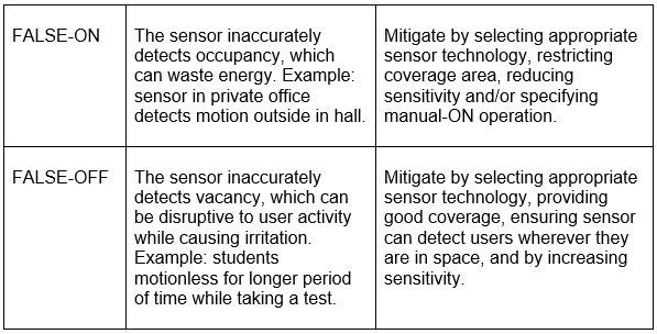
Designers must properly match sensors to applications to avoid issues such as false triggering, in which the sensor changes the lighting when it shouldn’t:
Time Delay
Time delay, which determines the amount of time before the lights turn OFF after detection of vacancy, is a significant adjustable sensor setting. Prevailing energy codes limit the time delay to 30 minutes, thought the latest energy codes are shortening this to 20 minutes.
Fluorescent lamps experience wear and tear on startup, so as the operating cycle decreases (hours per start), energy savings increase but lamp life decreases, particularly for instant-start systems. This may be mitigated by using long-life lamps and programmed rapid-start ballasts.
In contrast, frequency of starting imposes a negligible effect on LED product life. This theoretically allows time delays as short as 1-5 minutes, which can increase energy savings, though more sensors may be needed to avoid the potential for false OFF. Additionally, intelligent lighting control systems allow programming of time delay so that it changes based on time of day. For example, during the day, time delay might be 20 minutes. Afterhours, 5.
Related Lighting Controls Articles
Controlling Dual-Function Emergency Lighting - Lighting Controls Association
How Integrated Sensors in Luminaires are Changing Commercial Real Estate - OSRAM Sylvania Inc.

